


WDW-GDW High and Low Temperature Universal Testing Machine
Classification :
PRODUCT DETAILS
Suitable for tensile, compression, and bending tests on aluminum alloys and aluminum profiles, as well as transverse tensile, longitudinal shear, and torsion tests on aluminum alloy insulation profiles. Equipped with a high and low temperature test chamber, the equipment can conduct tests in ambient temperatures ranging from -40°C to 150°C. This equipment is used to test the tensile adhesion, fixed-elongation adhesion, and peel adhesion properties of various sealing materials and sealants.
Used for testing asphalt mixture specimens at specified temperatures: uniaxial compression testing, tensile testing, beam bending testing, flexural compressive rebound modulus, flexural stress compressive rebound modulus, compression stress, compression strain, compression deformation, low-temperature crack resistance, elastic stage compression stiffness modulus, compression failure stiffness modulus, vertical deformation, and horizontal deformation.
Based on standards:
Standards ASTMA370, ASTME4, ASTME8, ASTME9, ASTM D638, ASTM D882, ASTM D3039,ASTM D3479, ASTM E517,ASTM D695,ASTM D6641, ASTM D3410, ASTM D7791, ASTM D412, ISO6892, ISO527-3, ISO527-4, ISO7438, ISO7500-1, etc.
Product Features:
High-strength optical axis secures the upper crossbeam and work surface, forming a highly rigid portal frame mainframe:
A servo motor + reducer + timing belt + pulley + precision, zero-backlash ball screw transmission structure achieves vertical movement of the crossbeam. The test process is controlled by measurement and control software:
High-precision spoke-type/S-shaped force sensor with a force measurement accuracy of 0.5.
A variety of comprehensive test fixtures with pin connections and simple nut locking for easy operation;
Additional extensometers, displacement gauges, and large deformation gauges for precise material deformation measurement;
Powerful, fully digital, closed-loop, multi-channel measurement and control system with built-in testing methods and standards, automated test process control, data storage and export capabilities, and connectivity with multiple networked companies;
The bottom of the main unit is designed with wheel support and adjustable feet for easy positioning and subsequent adjustments;
The modular electrical control box facilitates troubleshooting;
Test force overload protection, safety limit protection, overcurrent and overvoltage protection, indicator light and voice prompts, and emergency stop switch;
Product Parameters:
| 1 | Maximum test force of sensor | 50kN |
| 2 | Testing machine level | Level 0.5 |
| 3 | Load measurement range | 0.4%-100%FS |
| 4 | Relative error of indication | ±0.5% |
| 5 | Test force resolution | 1/±500,000 F.S (resolution remains constant throughout) |
| 6 | Deformation measurement range | 0.2%-100% |
| 7 | Force Control Rate Adjustment Range | 0.005%-5%FS/S |
| 8 | Force Control Rate Control Accuracy | Within ±1% of the set value when the rate is <0.05%FS; within ±0.5% of the set value when the rate is >0.05%FS; |
| 9 | Deformation Rate Adjustment Range | 0.005-5%FS/s; |
| 10 | Deformation Rate Control Accuracy | Within ±1% of the set value when the rate is <0.05% FS/s; within ±0.5% of the set value when the rate is >0.05% FS/s. |
| 11 | Maximum Displacement Rate | 500mm/min; |
| 12 | Displacement Rate Control Accuracy | Within ±0.2% of the set value; |
| 13 | Constant Force, Constant Deformation, and Constant Displacement Control Range | 0.5%-----100% FS |
| 14 | Constant force, constant deformation, and constant displacement control accuracy | Within ±0.5% of the set value when the set value is ≥10% FS. Within ±1% of the set value when the set value is <10% FS. |
| 15 | Effective test span | 800mm |
| 16 | Maximum crossbeam travel distance | 1200mm |
| 17 | Power supply | ~220V ±10%, 50Hz (must be reliably grounded) |
| 18 | Motor Power | 750W |
| 19 | Main Unit Dimensions (L*W*H) | 1100x600x2200mm |
| 20 | Control Cabinet Dimensions (L*W*H) | 700*600*750mm |
| 21 | High/Low Temperature Test Chamber Temperature Control Range | -40℃~150℃ |
| 22 | High and Low Temperature Test Chamber Temperature Control Accuracy | ±0.1°C |
| 23 | High and Low Temperature Test Chamber Inner Dimensions | ≈390*300*580mm |
| 24 | Main Unit Weight | ≈800kg |
| 25 | Control Cabinet Weight | ≈30kg |
| 26 | High and Low Temperature Test Chamber Weight | Approximately 200kg |
Product Configuration (Subject to final order):
| Name | Content | Remarks |
| Load Frame | High-rigidity (4 columns + 2 screws), high-stability, dual-space, portal-type load frame | 1 unit |
| Drive System | AC servo speed-controlled motor and driver | 1 set |
| Measurement and Control System | Fully digital closed-loop, multi-channel, multi-functional, easy to operate | 1 set |
| Load Cell | 50kN, spoke-type load cell | 1 unit |
| High and Low Temperature Test Chamber | -40°C to 150°C (Imported Taikang Compressor) | 1 unit |
| Handheld Controller | Wired, LCD Display | 1 unit |
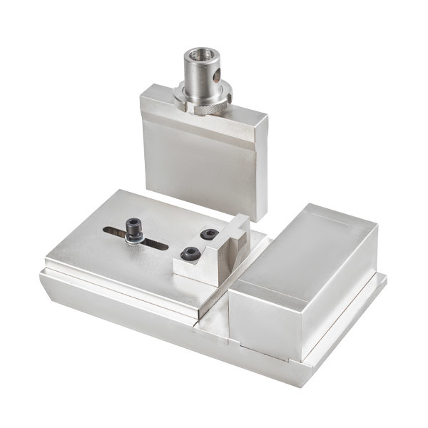
| Transverse Tensile Jig for Aluminum Alloy Insulation Profiles | GB/T 28289 Finishing, Nickel Plating, Heat Treatment | 1 set |
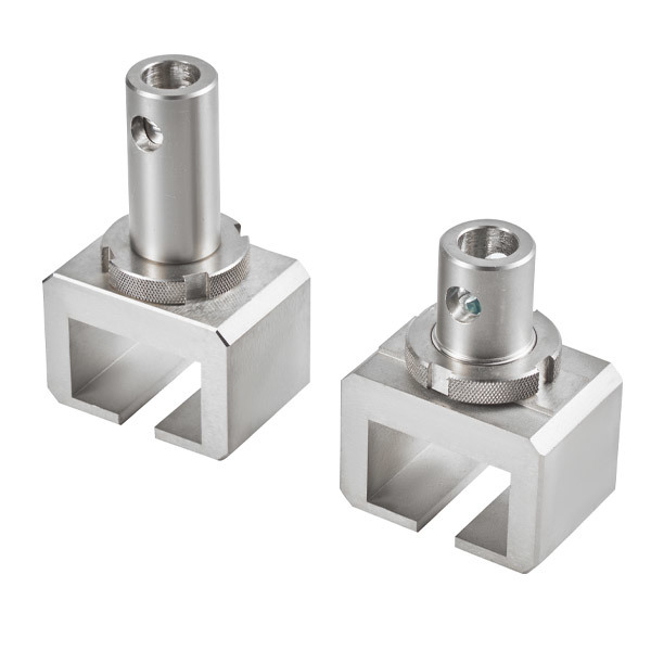
| Longitudinal Shear Jig for Aluminum Alloy Insulation Profiles | GB/T 28289 Finishing, Nickel Plating, Heat Treatment for Connectors | 1 set |
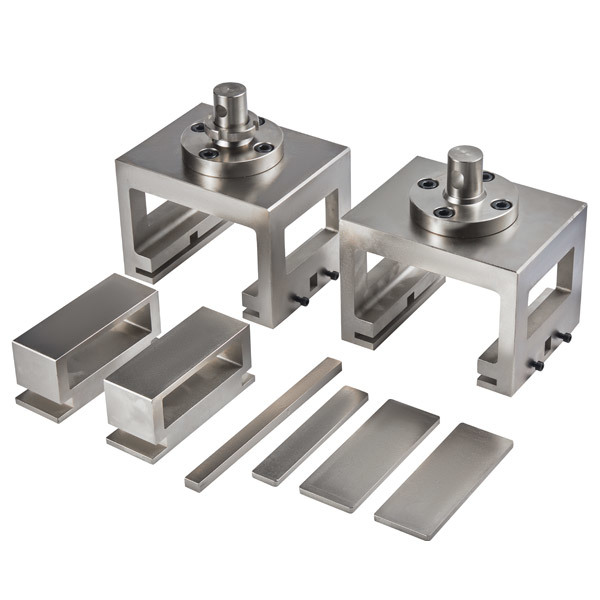
| Sealant Tensile Bond Strength Jig | GB/T 13477.8, GB/T 13477.10 & GB/T 13477.17 Figures 1 and 2: Finishing, Surface Nickel Plating, and Heat Treatment of Connectors | 1 set |
| Sealant Tensile Bond Strength Jig | GB 16776 Figure 2: Substrate Size 50*50mm, Finishing, Surface Nickel Plating, and Heat Treatment of Connectors | 1 set |
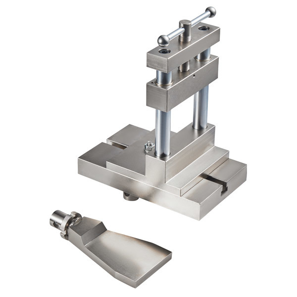
| Sealant Shear Strength Jig | JG/T 475, JG/T 471: Finishing, Surface Nickel Plating, and Heat Treatment of Connectors | 1 set |
| Asphalt Concrete Beam Bending Test | DL/T 5362 Finished, Nickel-Plated, Heat Treated | 1 Set |
| Asphalt Concrete Tensile Test Fixture | DL/T 5362 Finished, Nickel-Plated, Heat Treated | 1 Set |
| Compression Platen | φ100mm, Finished, Nickel-Plated, Heat Treated | 1 Set |
| Computer Measurement and Control Cabinet | Upper and lower levels, can accommodate a computer and fixtures, includes a 5-outlet power strip | 1 Unit |
| Computer | Brand | 1 unit |
| Technical data | Instruction manual, packing list, certificate of conformity | 1 set |
| Testing machine software | Chinese version/English version (optional) | 1 set |
Photos of fixtures (select as needed):
 |
 |
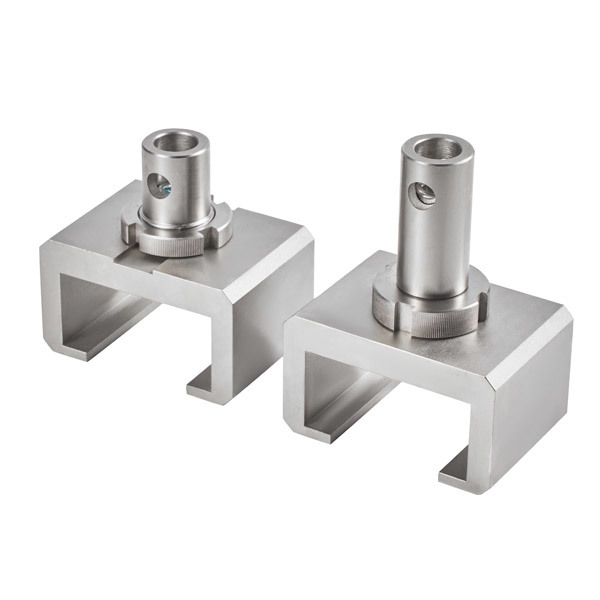 |
| Transverse Elongation of Insulation Profiles | Longitudinal Shear of Insulation Profiles | Tensile Bond Strength of Sealant (Specimen Size: 75*12mm) |
 |
 |
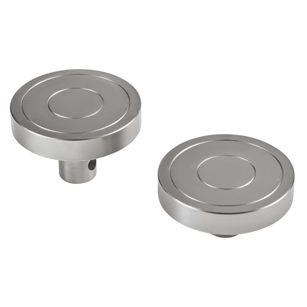 |
| Tensile Bond Strength of Sealant (Specimen Size: 50*50mm) | Compression Shear Strength Fixture | Compression Platen (Specimen Compression Strength or Equipment Calibration) |
Design and R&D
The overall design of the universal testing machine includes systematic designs such as the mechanical framework, sensor selection, control system architecture, electrical system, software functions, and the overall appearance of the machine.

Host:
The core components of the mainframe, such as the force-bearing frame and the tooling fixtures, are precisely processed through procedures like machining centers, milling, planing, and grinding. Special parts undergo quenching and tempering treatment to ensure that the structural performance of each mainframe meets the design requirements.

Component Heat Treatment

Sheet Metal Processing:
Sheet metal processing: The sheet metal parts for the testing machine are processed through laser cutting, bending, stamping, welding, grinding, and powder coating procedures.

Quality inspection of processed parts:
The quality of each component directly affects the performance of the entire machine. Before use, each component undergoes a series of quality inspection procedures. Usually, its size, tolerance, hardness, surface treatment, etc. are inspected.

Workshop assembly:
The mainframe components, drive motor, transmission mechanism, sensors, tooling fixtures, sheet metal, etc. are strictly assembled in accordance with the company's assembly procedures, and the corresponding data are archived for easy future reference.

Debugging Phase:
Conduct various standard tests, including load accuracy, displacement accuracy, force stability, control precision, and other related calibrations.

Machine inspection and file archiving:
Overall equipment inspection: Cleanliness inspection, impact inspection, rust prevention inspection, safety label inspection, completeness of configuration, etc.
File archiving: After the overall equipment inspection is completed, record the equipment number, configuration information of tooling and fixtures, sensor configuration information, equipment parameter settings information, etc. Both paper and electronic versions are archived for easy future reference.
| Factory inspection procedures | |||
| serial number | item | explain | "√" or "/" |
| 1 | Fixture appearance | The surface is clean, free of bumps and scratches. | |
| 2 | Appearance of the mainframe | The entire surface of the machine is clean, the paint finish is free of scratches, and the crossbeam has peeling paint. | |
| 3 | Equipment label | According to the order (strictly prohibiting any contamination during the pasting process) | |
| 4 | Host company logo sticker | According to the order (strictly prohibiting any contamination during the pasting process) | |
| 5 | Computer monitoring and control cabinet company logo sticker | According to the order (strictly prohibiting any contamination during the pasting process) | |
| 6 | Workbench rubber pad | Placed on the mainframe | |
| 7 | Computer control cabinet rubber pad | Placed inside the control and measurement cabinet | |
| 8 | Data cable label | Motor wires, encoder wires, power wires, sensor wires, board card wires, etc. | |
| 9 | Data cable winding | The board card cables are tangled with the RS232 cables, and the motor cables are tangled with the encoder cables. | |
| 10 | Force sensor connector | Each S-type sensor is equipped with a connector. | |
| 11 | Pin specification and quantity | 20KN model: φ12, 3 pieces; with S-type sensor: φ12, 4 pieces | |
| 12 | Overall inspection of the box panel fastening screws | ||
| 13 | Overall inspection of the fastening screws of the distribution box | ||
| 14 | Cleaning inside of the distribution cabinet and computer cabinet | Strictly prohibit any remaining connection terminals or similar items. | |
| 15 | Computer and Accessories Configuration | Computer, monitor, keyboard, mouse, mouse pad | |
| 16 | Appearance of computer accessories | ||
| 17 | Packing list verification | ||
| 18 | Attached is the packaging. | Pack properly and protect from surface scratches | |
| 19 | Computer packaging | Clean and undamaged | |
| 20 | Mainframe packaging | Safety Loading and Unloading Sign | |
| Inspector (Signature): | |||
| Date: | |||
| Form filling instructions: Mark "√" for "Pass Inspection", mark "√" for "Pass Inspection of Accessories" on the packing list, leave blank if no such item exists, and submit it to the warehouse for filing after self-inspection is completed. | |||
Packaging And Delivery

Product Application

APPLICATION FIELD

Aerospace
Automobile Manufacturing
Mechanical Manufacturing
Electronic Components
Textile Industry
Wires and Cables
CERTIFICATES

Software Registration No.11208041

Pressure Testing Machine Embedded System V1.0

Soft Registration No.11208039

Constant Temperature and HumiditySystem Control Software V1.0

A Kind of Door andWindow Performance Testing Equipment

A Concrete lmpermeability Test Device

A Temperature and Humidity Control Device

A Hydraulic Universal Testing Machine
FAQ
Q:Does the product have quality inspection before loading?
Q:Can l go to your factory to visit?
Q:How many countries you already exported to?
Q:How long does your delivery time take?
Q:What product information do l need to provide?
Q: Can we get the some samples? Any charges?
RELATED PRODUCTS
GET A FREE QUOTE
CONTACT US
Zhongnan Industrial Smart City, 858 Zidong Avenue, Tianqiao District, Jinan City, Shandong Province
GET A FREE QUOTE