


WDW Coil Coating Rubber Plastic Universal Testing Machine
Classification :
PRODUCT DETAILS
This program is used for mechanical property testing of non-plate-shaped non-metallic materials such as waterproof membrane, coating, sealant, rubber, plastic, etc. (the main parameters are: tensile property, tear property, maximum peak tensile force, second peak tensile force, elongation at maximum peak, elongation at second peak, seam peel strength, seam tear strength, tensile strength, elongation at break, stress at constant tensile strength, elongation at constant stress, tensile stress at yield point, elongation at yield point, and permanent set at break).
According to the standard:
| GB/T 16491 Electronic Universal Testing Machine | GB 18242 Elastomer-Modified Asphalt Waterproofing Membrane |
| JJG 475 Electronic Universal Testing Machine | GB/T 328.1-27 Test Methods for Building Waterproofing Membranes |
| GB/T 2611 General Technical Requirements for Testing Machines | GB 18243 Plastomer-Modified Asphalt Waterproofing Membranes |
| JJG 139 Tensile, Compression, and Universal Testing Machines | GB 18967 Modified Asphalt Polyethylene-Based Waterproofing Membranes |
| GB/T 14686 Petroleum Asphalt Glass Fiber-Based Waterproofing Membranes | GB/T 23457 Pre-laid/Wet-laid Waterproofing Membrane |
| GB 12952 2011 Polyvinyl Chloride Waterproofing Membrane | GB 12953 Chlorinated Polyethylene Waterproofing Membrane |
| GB 27789 Thermoplastic Polyolefin (TPO) Waterproofing Membrane | GB/T 18173.1-4 Polymer Waterproofing Materials |
| JC/T 504 Aluminum Foil Faced Petroleum Asphalt Waterproofing Membrane | JT/T 536 Asphalt Plastomer (APP) Waterproof Membrane for Roads and Bridges |
| JC/T 645 Butylene Rubber Waterproof Membrane | JC/T 684 Chlorinated Polyethylene-Rubber Blend Waterproof Membrane |
| JC/T 690 Asphalt Composite Flexible Waterproof Membrane | JC 840 Self-Adhesive Rubber Asphalt Waterproof Membrane |
| JC 898 Self-Adhesive Polymer-Modified Asphalt Polyester Waterproof Membrane | JC/T 974 Modified Asphalt Waterproofing Membrane for Roads and Bridges |
| GB/T 16777 Test Methods for Building Waterproof Coatings | GB/T 23445 Polymer Cement Waterproof Coatings |
| JC/T 975 Waterproofing Coatings for Roads and Bridges | JB/T 7797 Rubber and Plastic Tensile Testing Machine |
| GB/T 31357 General Technical Specifications for Composite Rubber | GB/T 1040.1-5 Plastics Determination of Tensile Properties |
| GB 16776 Silicone Structural Sealant for Buildings | JC/T 976 Sealant for Road and Bridge Joints |
| JC/T 881 Sealant for Concrete Joints | JC/T 882 Sealant for Curtain Wall Glass Joints |
| JC/T 884 Sealant for Metal Sheets | JC/T 885 Anti-Mold Sealant for Buildings |
| JG/T 475 Silicone Structural Sealant for Curtain Walls | GB/T 14683 Silicone and Modified Silicone Building Sealant |
| GB/T 23261 Building Sealant for Stone | GB/T 29755 Elastic Sealant for Insulating Glass |
| JT/T 740 Pavement Heating Sealant | JG/T 471 Elastic Sealant for Insulating Glass for Doors, Windows, and Curtain Walls |
| GB 24266-2009 Silicone Structural Sealant for Insulating Glass | GB/T 24267-2009 Flame-Retardant Sealant for Buildings |
| JC/T 482-2003 Polyurethane Building Sealant | JC/T 483-2006 Polysulfide Building Sealant |
| JC/T 484-2006 Acrylate Building Sealant | JC/T 485-2007 Elastomeric Sealant for Building Windows |
| GB/T 528 Vulcanized or Thermoplastic Rubber | GB/T 529 Vulcanized or Thermoplastic Rubber - Determination of Tear Strength |
| GB/T 7762 Vulcanized or Thermoplastic Rubber | GB/T 13936 Vulcanized Rubber |
| GB/T 15254 Vulcanized Rubber - 180° Peel Test to Metal | GB/T 16586 Vulcanized Rubber - Determination of Adhesion Strength to Steel Cord |
| GB/T 25270 Rubber and Plastics - Tension, Flexure, and Compression Testing Apparatus | GB/T 13477.8 Test Methods for Building Sealing Materials |
| GB/T 13477.10 Test Methods for Building Sealing Materials | GB/T 13477.17 Test Methods for Building Sealing Materials |
Product Features:
High-intensity optical axis
Fixing the upper crossbeam and work surface to form a highly rigid portal frame
Servo motor The transmission structure uses a speed reducer, synchronous belt, pulley, and precision, backlash-free ball screw to achieve vertical movement of the crossbeam. The test process is controlled by measurement and control software: High-precision spoke-type/S-type force sensors, with a force measurement accuracy of 0.5; >
A variety of comprehensive test fixtures with pin connections and simple nut locking for easy operation;
Additional extensometers, displacement gauges, and large deformation gauges for precise material deformation measurement;
Powerful fully digital closed-loop, multi-channel measurement and control system,
with various built-in testing methods Standard, automatic control of the test process, data saving and export, and networking with multiple companies; The bottom of the main unit is designed with a wheel and adjustable leveling feet for easy positioning and subsequent adjustments.pan>
Modular electrical control box for easy troubleshooting;
Test force overload protection,,, ,Indicator lights indicate operating status, voice prompts, and an emergency stop switch;
Product Specifications:
| 1 | Maximum test force of sensor | Standard 5kN (optional value below 50kN) |
| 2 | Testing machine level | Class 0.5 |
| 3 | Load measurement range | 0.4%-100%FS (Class 0.5) |
| 4 | Relative error of indication | ±0.5% (Class 0.5) |
| 5 | Test force resolution | 1/±500,000 F.S (resolution remains constant throughout the entire range) |
| 6 | Deformation Measurement Range | 0.2%-100% |
| 7 | Force-Control-Rate Adjustment Range | 0.005%-5%FS/S |
| 8 | Force-Control-Rate Control Accuracy | Within ±1% of the set value for rates <0.05%FS; within ±0.5% of the set value for rates >0.05%FS |
| 9 | Deformation Rate Adjustment Range | 0.005-5% FS/s; |
| 10 | Deformation Rate Control Accuracy | When the rate is less than 0.05% FS/s, it is within ±1% of the set value; When the rate is greater than 0.05% FS/s, it is within ±0.5% of the set value; |
| 11 | Maximum Displacement Rate | 600mm/min; |
| 12 | Displacement Rate Control Accuracy | When the rate is less than 0.05% FS/s, it is within ±0.5% of the set value; |
| 13 | Constant force, constant deformation, and constant displacement control range | 0.5%-----100%FS |
| 14 | Constant force, constant deformation, and constant displacement control accuracy | Within ±0.5% of the set value when the set value is ≥10%FS. Within ±1% of the set value when the set value is <10%FS. |
| 15 | Maximum column spacing | 450mm |
| 16 | Crossbeam maximum travel distance | 1100mm (customizable) |
| 17 | Large deformation measurement range | 10-1000mm |
| 18 | Power supply | ~220V ±10% 50Hz (must be reliably grounded) |
| 19 | Motor power | 750W |
| 20 | Main unit dimensions (L*W*H) | 760x450x2100mm |
| 21 | Control Cabinet Dimensions (L*W*H) | 700*600*750mm |
| 22 | Main Unit Weight | 350kg |
| 23 | Control Cabinet Weight | 30kg |
Product Configuration (Subject to final order):
| Name | Content | Remarks |
| Load Frame | High rigidity (4 columns + 2 lead screws), high stability, dual-space, portal load frame | 1 unit |
| Drive system | AC servo speed control motor and driver | 1 set |
| Measurement and control system | Fully digital closed-loop, multi-channel | 1 set |
| Load cell | 5KN, spoke-type | 1 unit |
| Handheld controller | Wired, LCD display | 1 unit |
| Corrugated Tensile Grip | Clamp body: aluminum profile (surface oxidized), clamping plate and pressure plate: 45# steel (surface nickel-plated, heat-treated). Clamping width: 100mm, clamping depth: 75mm. | 1 set |
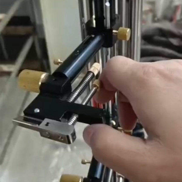
| Ejector Ripping Grip | Finely machined, nickel-plated, heat-treated connectors | 1 set |
| Self-locking Clamp | Finely machined, nickel-plated, heat-treated connectors | 1 set |
| Clamp body | Finely machined, nickel-plated, heat-treated connectors | 1 set |
| Jaws | 0-7mm | 1 set |
| Compression attachment | 220*220mm, nickel-plated, heat-treated | 1 set |
| Large deformation extensometer | Precision, rotary, dual encoder | 1 set |
| Measurement and control cabinet | Two layers (can accommodate a computer, fixtures, etc.) | 1 unit |
| Computer | Mainstream brand | 1 unit |
| Technical Data | Instruction Manual, Packing List, Certificate of Conformity | 1 set |
| Testing Machine Software | Chinese Version | 1 set |
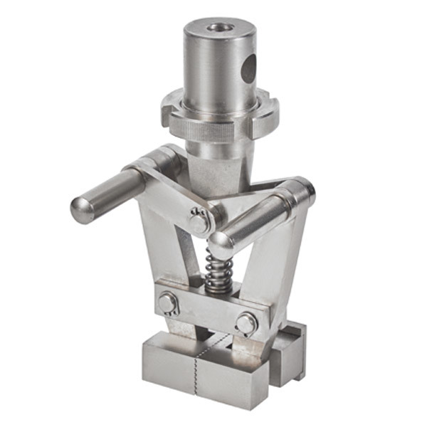
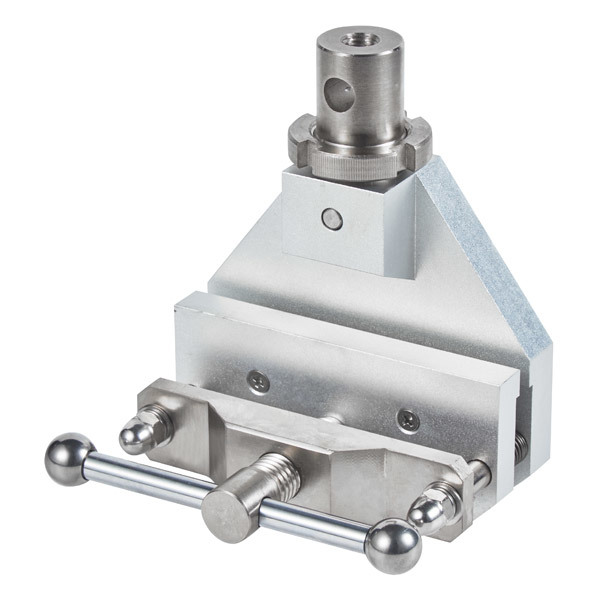
Photos of Fixtures (Select as Needed):
 |
 |
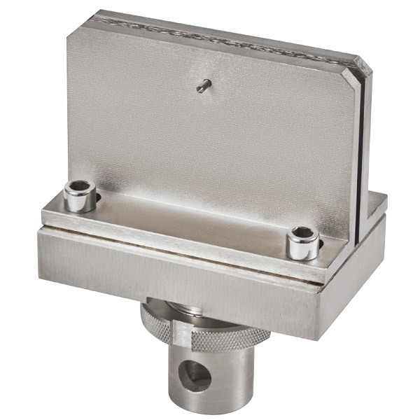 |
| Self-locking Clamp (300N sheet specimens) | Corrugated Grips (300N sheet specimens) | Nailbar Tear Grips |
 |
 |
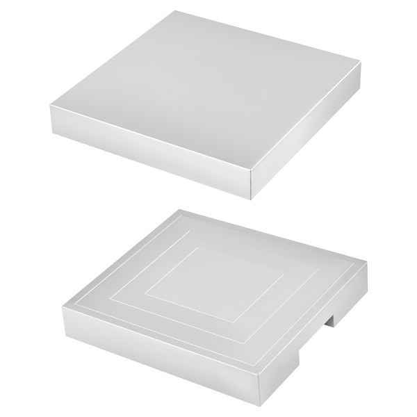 |
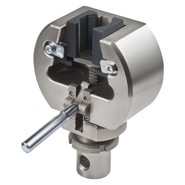
| Wedge Grips (Hard Sheet Specimens) | Extensometer (In-Gauge Elongation Testing of Sheet Specimens) | Compression Platen (Specimen Compression Strength or Equipment Calibration) |
Design and R&D
The overall design of the universal testing machine includes systematic designs such as the mechanical framework, sensor selection, control system architecture, electrical system, software functions, and the overall appearance of the machine.

Host:
The core components of the mainframe, such as the force-bearing frame and the tooling fixtures, are precisely processed through procedures like machining centers, milling, planing, and grinding. Special parts undergo quenching and tempering treatment to ensure that the structural performance of each mainframe meets the design requirements.

Component Heat Treatment

Sheet Metal Processing:
Sheet metal processing: The sheet metal parts for the testing machine are processed through laser cutting, bending, stamping, welding, grinding, and powder coating procedures.

Quality inspection of processed parts:
The quality of each component directly affects the performance of the entire machine. Before use, each component undergoes a series of quality inspection procedures. Usually, its size, tolerance, hardness, surface treatment, etc. are inspected.

Workshop assembly:
The mainframe components, drive motor, transmission mechanism, sensors, tooling fixtures, sheet metal, etc. are strictly assembled in accordance with the company's assembly procedures, and the corresponding data are archived for easy future reference.

Debugging Phase:
Conduct various standard tests, including load accuracy, displacement accuracy, force stability, control precision, and other related calibrations.

Machine inspection and file archiving:
Overall equipment inspection: Cleanliness inspection, impact inspection, rust prevention inspection, safety label inspection, completeness of configuration, etc.
File archiving: After the overall equipment inspection is completed, record the equipment number, configuration information of tooling and fixtures, sensor configuration information, equipment parameter settings information, etc. Both paper and electronic versions are archived for easy future reference.
| Factory inspection procedures | |||
| serial number | item | explain | "√" or "/" |
| 1 | Fixture appearance | The surface is clean, free of bumps and scratches. | |
| 2 | Appearance of the mainframe | The entire surface of the machine is clean, the paint finish is free of scratches, and the crossbeam has peeling paint. | |
| 3 | Equipment label | According to the order (strictly prohibiting any contamination during the pasting process) | |
| 4 | Host company logo sticker | According to the order (strictly prohibiting any contamination during the pasting process) | |
| 5 | Computer monitoring and control cabinet company logo sticker | According to the order (strictly prohibiting any contamination during the pasting process) | |
| 6 | Workbench rubber pad | Placed on the mainframe | |
| 7 | Computer control cabinet rubber pad | Placed inside the control and measurement cabinet | |
| 8 | Data cable label | Motor wires, encoder wires, power wires, sensor wires, board card wires, etc. | |
| 9 | Data cable winding | The board card cables are tangled with the RS232 cables, and the motor cables are tangled with the encoder cables. | |
| 10 | Force sensor connector | Each S-type sensor is equipped with a connector. | |
| 11 | Pin specification and quantity | 20KN model: φ12, 3 pieces; with S-type sensor: φ12, 4 pieces | |
| 12 | Overall inspection of the box panel fastening screws | ||
| 13 | Overall inspection of the fastening screws of the distribution box | ||
| 14 | Cleaning inside of the distribution cabinet and computer cabinet | Strictly prohibit any remaining connection terminals or similar items. | |
| 15 | Computer and Accessories Configuration | Computer, monitor, keyboard, mouse, mouse pad | |
| 16 | Appearance of computer accessories | ||
| 17 | Packing list verification | ||
| 18 | Attached is the packaging. | Pack properly and protect from surface scratches | |
| 19 | Computer packaging | Clean and undamaged | |
| 20 | Mainframe packaging | Safety Loading and Unloading Sign | |
| Inspector (Signature): | |||
| Date: | |||
| Form filling instructions: Mark "√" for "Pass Inspection", mark "√" for "Pass Inspection of Accessories" on the packing list, leave blank if no such item exists, and submit it to the warehouse for filing after self-inspection is completed. | |||
Packaging And Delivery

Product Application

APPLICATION FIELD

Aerospace
Automobile Manufacturing
Mechanical Manufacturing
Electronic Components
Textile Industry
Wires and Cables
CERTIFICATES

Software Registration No.11208041

Pressure Testing Machine Embedded System V1.0

Soft Registration No.11208039

Constant Temperature and HumiditySystem Control Software V1.0

A Kind of Door andWindow Performance Testing Equipment

A Concrete lmpermeability Test Device

A Temperature and Humidity Control Device

A Hydraulic Universal Testing Machine
FAQ
Q:Does the product have quality inspection before loading?
Q:Can l go to your factory to visit?
Q:How many countries you already exported to?
Q:How long does your delivery time take?
Q:What product information do l need to provide?
Q: Can we get the some samples? Any charges?
RELATED PRODUCTS
GET A FREE QUOTE
CONTACT US
Zhongnan Industrial Smart City, 858 Zidong Avenue, Tianqiao District, Jinan City, Shandong Province
GET A FREE QUOTE